Saturday, June 27, 2015

Pimp Your Watch (a.k.a. WatchPlus update 1.04)

I finally did it - took a break from electronics and stuff, sat on my ass and did the update I promised quite a while ago.

Main features of the new update are:
- Added option to use an image from the watch Gallery as a background
- Added 12 color options (there were no color options before)
- Added option to display seconds

In my opinion seconds are totally pointless and changing the foreground color may be cool but makes visibility worse. But, people asked for these, I promised and delivered.
The idea to use Gallery images as a background was really nice one though . BIG thanks to the dude who suggested it. I only have his e-mail though, so I am not shouting it out :)

The outcome is that you can seriously pimp your watch now :)
And, if a picture is worth a thousand words, here are 15K words:


You know what's funny - I am not going to hate Samsung in this post! Maybe just a little.
I expected to face lots of troubles implementing these features, but at the end they turned up fairly straight-forward.

Well, the 1st attempt to get pictures from Gallery failed miserably. I tried reading the files in the images folder, loading the images and showing them to the user to pick from. It worked, but it was horribly slow. That was because it had to stretch many large images at runtime. I didn't know how to pre-scale an image back them (remember, I am still a noob in this web tech thing).
Fortunately, there was an alternative way - pretty much an API call, which invokes the system default's image picker. There even is a sample how to do that in their SDK.
Of course, I still had to scale the resulting image (the background the user has chosen), but I figured out how to do that anyway (more on that later).

The other "challenge" I expected was how to colorize images - some of the clock styles use bitmap images with built-in light effects in them. So, to change their color I had to process the image and colorize its pixels.
I found many examples how to do that on the web (it is just common HTML5 tech, not Samsung-specific). The pleasant surprise was that it just worked (with my experience with Samsung so far I expected something will go wrong along the way).

The process of "processing" an image looks like this:
- create an offscreen canvas
- draw the image in it (scaling is possible)                                                          (1)
- get a copy of the canvas pixels (an array of RGBA values)                                 (2)
- process the pixels in the array any way you want (colorize them in my case)
- "draw" the array of pixels back to the canvas                                                     (3)
- get an "image URL" from the canvas!                                                               (4)
- create a new image, and tell it to load from that URL (as if it loads from file)       (5?)

If you're wondering what these numbers in parenthesis are - I counted the number of (unnecessary) memory copies in the process. Basically you copy the image twice just to get access to its pixels, and then 2-3 times to convert the result back to an image!

The game programmer in me vomited a little.

I'm pretty sure there is an explanation why it must be done like this, but honestly - I don't want to know.

Still, I was surprised that it actually worked ... and not surprised at all that it was slow.
Initially, changing the color of the clock took above 2 seconds! To be honest, it wasn't that bad, just a shame.
I started thinking of performance optimizations, at some point I caught myself thinking whether it will make a difference if I skip pixels with alpha 0 (because they should be already in the CPU cache) ... then I stopped and told myself "Dude, seriously? This is not game dev, not C++ and not PC. This is javascript running god-knows-how (interpreted?) on an exotic platform. Besides, processing the pixels is not what takes the time, the 4-5 memory copies are. Or at least I would guess so without profile data to prove it."
I could profile it with debug prints, I could delay it over several frames, but it just wasn't worth it.
I ended up with some quick-and dirty optimizations which brought it to about a second. Far from ideal, but in reality - who cares!.
At least it is not Samsung to blame here - looks like the WHOLE WEB works like this.

Ultimately, coding the new update took me less than 2 days. Not so bad.

Preparing the update for submission took me another half a day!
Why?
Because I had to prepare new screenshots and the fucking Russian translation!
That Russian translation was a big mistake.
I did it, because Russians are used to see software translated in their language. Several of them asked for translation. So I thought "why not - it would probably increase the sales in Russia".
It didn't.
Instead, sales in Korea grew significantly!
I doubt that is some kind of butterfly effect - more likely Koreans liked the analog clock styles which came with the same update. Or ... my app has been promoted in Korea (I have no way of knowing that) without Samsung telling me.
Anyway, disappointed by our brother Russians, I cut some corners and used the English screenshots in the Russian version (except for the preferences). The difference is only the date anyway.
And this time I translated the texts myself (with the help of google translate, which is crap), instead of bugging my Russian speaking colleagues for help. I don't care.

Finally, all done, checked and double-checked, I go to Samsung's web site and hit the "Update" button. Guess what happened? Nothing. Tried few more times - nope, the "Update" button didn't work!
I laughed out loud.
At the end, logging out and back in to their site solved it, so I was able to submit the update.
If nothing goes wrong, it should be live in about a week.

Thursday, June 25, 2015

Brace yourselves, the Money are coming!

10 days ago, I received this e-mail:


Before I jump on Samsung, let me slap Google first, just for warm-up. I went to my Google mail web UI to get the above screenshot and see when exactly it came, so I could start the 1st sentence in this post accurately. And here is how the line in my Google web UI looked like:


Ok, 9:09 am. ON WHICH DAY?!? Seriously, they tell you the time of the message, but not the day - for the past 10 days or so?!? Messages from June 11th and older have a date instead of time, so it is not like they just forgot to add the date. There is actually a special handling in their code, written by a real programmer and probably designed by a real designer and passed real QA, which makes the timestamps work like this. Fucking amazing!

But, screw Google (for now), this post is all about Samsung.

First, in case you haven't read my previous posts carefully - "Settlement Report" is supposed to come when your profit from selling apps on the Samsung market exceeds $150 and they are about to send you the money.
To cut your enthusiasm early - nope, I still haven't received any money ... yet. But they are coming.
After few days without payment, I decided to write Samsung and ask them when to expect the money. Here is their answer:


• Here is the answer to your enquiry.
Dear Customer,

Thank you for contacting us. We appreciate the opportunity to assist you.

Regarding your inquiry, we would like to inform you that if you have the settlement report confirmed your revenue is exceeded 150 USD, then you may expect the payment to be paid to your PayPal account at the end of the month around 30st. If you do not get the payment by then, please contact us again with screenshots of the settlement report. We will further look into the matter for you.

Besides, please be noted that the settlement cycle begins on 15th of every month.

We hope this information could be useful.

Ok, so June 30th. No rush.

But:

- Why on earth are they sending me an e-mail on June 15th to tell me that they are about to send me some money 2 weeks later?!? What is the point of this report?

- What the fuck do they mean by "If you do not get the payment by then"? Does that happen too? And why am I surprised?

- I fail to explain to myself how "settlement cycle begins on 15th every month" relates to "Period : Apr 19, 2015 ~ May 31, 2015". This is more confusing than women's cycles and periods!

- This one is funny too: "Settlement Status : Settlement Confirm", "Estimated Transfer Payment : USD 472.70". Which one is it - Confirmed or Estimated?!?


And now, let's talk about numbers.
I have mentioned before, that Samsung offers plenty of information on their developers' website.
I am about to present it to you in more details.

There are "Accounting" and "Statistics" tabs in their site's main UI.

I think I have ranted about "Statistics" enough already (see my older posts). But, for completeness, check out how my "daily downloads" look like today:


"Accounting" has 3 sub-tabs - "Sales Summary", "Financial Report" and "Settlement Report".

As I mentioned in my previous post, "Sales Summary" gives you detailed information about your sales, but does not include any totals. According to Samsung:
  • Sales Summary is a monthly performance report that updates daily the revenue through SAMSUNG Galaxy Apps and the income of the seller.
    Although the report can be queried monthly, the data are updated daily.
    Therefore, the users can query the updated performance everyday.
So I made a little program to summarize the data and present it in a decent way. I downloaded the data once per day since June 14th. Today it looks like this:


"Updates daily", my ass. More like "every couple of days, at random times".
Now if someone can explain me the relation between these numbers and the ones in the "Statistics" image before - be my guest. I am pretty sure neither of them reflect the truth.

Here is how my "Financial Reports" look like for April and May:


Now, time for observations:

- "Sales Summary" (remember, this is their data, my app just displays it properly) says $211 for April and $466 for May. "Monthly Reports" (their other data) say $88 for April and $400 for May. Cool, huh? I actually have an explanation for this - it looks like "Financial Reports" do not cover the last week (or so) of the month. Since I released my app on April 19th, the differences for April are big.

- If you sum "Financial Reports" for April and may you get $489.76. The "Settlement Report" says $472.70. Pretty close, but not the same. Again, financial reports don't reflect the last week of the month, and maybe Settlement report does? But if it did it should be $211 + $466, shouldn't it? More likely, it is like the financial reports, but minus some payments which are not yet received by Samsung (they say some mobile operators can pay as late as 6 months after). I don't know.

- Oh, and just to complete the picture, according to their "Statistics", here are the monthly sales totals before taxes and commissions: April: $282.45; May: $628.65; June: $714.73 (Total: $1625.83).

So, Samsung generously provide me with at least 4 different ways to get some information about how my app is doing. And they all show 4 different results! At the end, all I get is confusion and headache.
If they only gave me one, I would have no other option but to accept it as "the truth" and move on (and several of my blog posts would not exist).

The real truth is: Their data (or at least the way it is presented) is a big fucking mess, just like their software.

Monday, June 22, 2015

Internet connected LCD

A while ago I told you about my smart home setup. Part of it was a cheap Nokia 3310 LCD displaying the time and room temperature. Then I told you about the ESP8266, a microcontroller with built in WiFi.
Today, after a lot of struggling, I finally managed to combine these 2 together. Now I have an internet connected LCD:

Two ESPs died in the process - no idea how, they just died. RIP. Its time to order some more, because I have only one left.

Originally, I used the Adafruit library on the Arduino. So, the first thing I tried was to try to compile it for the ESP. Unfortunately, it didn't compile and at that time porting it seemed non-trivial. So I looked up for alternatives. And found out here that these examples should just work on the ESP.
The first problem is that these examples require 5 GPIO pins and the ESP-01 only has 4.
But, in the description of this library it says you can connect Chip Select to ground (because I don't have other devices sharing the SPI bus) and Reset to the Reset of the ESP. Which would mean it would only take 3 GPIO pins and leave me 1 spare!
So, I tried, compiled the examples and ... they didn't work. Just a blank screen. I double and triple checked my connections, my code ... everything was fine.
In desperation I tried the same examples, but with the Arduino instead with the ESP. Surprise, surprise, they didn't work on the Arduino either.
So I took the Adafruit's library and example (which work on the Arduino) and started comparing it with the code I was using.
Ultimately, I found out the following:
- You have to call "set contrast" again after initialization of the LCD for some reason (the initialization itself sets it). No idea why. But that was what caused the playground samples not to work. Maybe it is only the Chinese LCD + breakout I am using.
- It is indeed OK to connect "chip select to ground"
- It is NOT OK to connect Reset to the reset pin of the ESP. It needs a reset after the ESP has started. I am guessing it is because the ESP outputs stuff on its pins on boot, which might confuse the LCD.

So, for now I have 2 options - to waste the 4th GPIO pin with the sole purpose to reset the LCD at startup and stay HIGH from then on ... or to somehow reset the LCD by other means.
For the moment I just added another push button to reset the LED manually and made the code wait for 2 seconds on startup (so I have time to press it). It is far from ideal - as I have said before, finished projects should only have an on-off switch and that's it.
I believe it is possible to replace the push button with or more 555 timer chips, I just have no idea how ... yet.

Still, I now have an internet connected LCD and a spare GPIO pin. I have no idea how I am going to use them, but it is cool by itself.

The next step would be to actually port the Adafruit library - I now know enough about its inner workings, so it shouldn't be a problem.


Saturday, June 20, 2015

Back to the ... bread ... board!

In my previous post I was excited to let you know about the ESP8266 breakout I did. And I'm still proud of it.
But then I discovered two things:
- You can use the TX and RX pins as GPIO pins! This means you can youse 4 GPIO pins on the cheapest ESP8266-1 module, not 2. That makes it even more useful (you can control up to 4 things over the internet now, not just 2, using a single ESP board).
- The ESP is incredibly picky. It doesn't like when stuff is connected to its GPIO pins when its booting. If you have 4 LEDs connected to its GPIO pins the chance is it won't boot. And, it depends on the type of the LEDs. Red ones tend to cause most trouble. I am not joking.

So, my cute little breakout is now a bit obsolete - it is still useful, but not ideal.
I was presented a new challenge - to find a convenient and reliable way to use all 4 pins on the smallest ESP.
The problems:
- When booting, all 4 GPIO pins should be floating
- When in "programming mode" GPIO0 should be low, RX and TX should be connected to USB2TTL
- When in "running mode", all 4 pins should be connected to whatever I want to connect them to (LEDs, motors, relays, sensors, etc.)
- As soon as uploading a new program is finished, the ESP goes to "running mode" and starts executing that program. This is while its pins are still in "programming mode" configuration.
- I need a "development setup" setup where I can repeatedly toggle between boot/programming/running mode (so I can upload and test new code) and a "final setup" for the completed projects (it still has to boot with all pins floating and later toggle them to "running mode").

Long story short, my "development setup" looks like this:
After buying the proper switches (called "2P3T switches) it was fairly easy. Each switch controls 2 independent circuits and has 3 different positions. The only problem was that these switches were not breadboard/protoboard friendly, so I had to make little "breakouts" for them. Special thanks to a friend of mine who cut the PCBs for me, to make it possible.
Now I have the usual reset button, power on/off switch and two 3-state switches. These 2 toggle 2 pins each between programming/boot/running mode. The left one is for GPIO0 and GPIO2 and the right one is for TX/RX (a.k.a. GPIO1 and GPIO3). I used 2 separate switches so I can control TX/RX separately. So, I can still use them as TX/RX (e.g. for debug output to PC during development).

The problem that the program starts running as soon as the upload is completed turned out to be not a real problem. At first I was afraid outputting HIGH through RX/TX pins could cause some damage (to the USB2TTL board or to my laptop's USB). There was one way to find out - I put on protective glasses, helmet, had a fire extinguisher ready, crossed my fingers and just tried it. Nothing bad happened. You can even see the USB2TTL's lights blinking when my program sends high/low through TX/RX. I only had to use a pull down resistor between GPIO0 and ground instead of simple wire, because outputting high signal to GPIO0 (which is connected to ground in programming mode) resulted in a short circuit. Fortunately, it didn't blow the ESP, just made it reset.

So, now developing for the ESP is easy - i put the 2 switches to "neutral", turn the power on, then switch to "programming mode" (both switches to the left), upload a new program, flip one or both switches to the right when the program is running if needed. For corrections, I just flip the 2 switches back to the left, hit the reset button and upload the new program. It's not as easy as with the Arduino, but it's easy enough.

Now, the "final setup" is a bit more tricky. I could probably go with a few 2-state switches - an on/off switch and 1-2 switches to toggle the GPIO pins between "boot mode" and "running mode". But that would be kind of lame. Final products only need to have an on/off switch and that's it. And, when you turn it on, it would need to boot the ESP with all GPIO pins floating and then reorganize its pins to "running mode". After some fiddling and with the help of a 555 timer chip and 2x relay chips I came up with this prototype:

Well, right now there is no "on/off" switch, you just plug the battery, but that's just because the switches I have do not fit the breadboard very well and cause bad connections. When soldered on a proto board they will be a not-an-issue.
What happens now is when I turn the power on the ESP boots and after a second or so the timer kicks in, turns the relays on and they switch the 4 pins into "running mode". Smooooth :)

Btw, these 555 timer chips are awesome little toys, they can do so many things. And they cost like $0.75. For example, I plan to use one to make a horn for my electric scooter and another one to make blinkers for it. If you're into electronics and don't know what a 555 chip is (as I didn't until few days ago) - look it up, there is plenty of info and plenty of different usages.

Oh, and the current test makes the ESP create a WIFI hotspot, you connect to it (from a phone/laptop/tablet), and you can control the 4 LEDs from a web browser. I also tried connecting the ESP to my router instead of creating a hotspot - no problems.

So, now I can control 4 pins on a single ESP82266-1 from anywhere in the world :)
This means I could turn 4 lights/appliances on/off, drive an RC car (two motors in both directions) and whatnot ... over the internet. Using components that cost like $5 total. Nice, huh?

The next step is to turn the above prototype into a much more compact breakout, but I am not in the mood for tricky soldering today ... and I'd like to wait a little longer before I do that, just in case I get some other ideas in the meantime.


Monday, June 15, 2015

Screw Samsung, I am doing it myself!

In my previous pos I told you how bad Samsung's Seller Office is (the site that developers are supposed to use to add/update apps, view downloads/sales statistics, buyer comments, etc.)

One thing I complained about, was that there was no easy way to tell actually how much your app has sold. There are "Statistics" and "Accounting" sections on this site.

Statistics break way too often - in my last post I complained they are broken for the 3rd time, guess what - they are still broken.
When they work, they don't reflect all the data (I have proven that in my last post) and the numbers they give you are "net" sales - before Samsung cuts their 30%, some countries take VAT, some mobile carriers take a percentage too. At it varies from country to country and from carrier to carrier.
Still, when they work, they are somehow useful as a rough estimation.

Accounting data seems to be more accurate. I guess they had the common sense to put someone with at least half a brain in charge of accounting data. But whoever designed the features on the site ... well, let's say he is not the brightest star in the sky. Not by a long shot.

So, until now, I had to choose between Statistics that don't work and accounting data that looks accurate but is too raw - too much useless information and no overview (e.g. no "Total" fields).

There is one way though - in the accounting data, there is this button labeled "Excel". When you click it - surprise, surprise - it downloads an excel file, containing the same raw information. It takes some search-and-replacing to transform the data they give you to something Excel actually recognizes as numbers. But then, you can select the last column and, lo and behold, you get a total number of dollars. For that month. Repeat this for all months, sum the totals and you get the total amount of money your app has made! It takes less than half an hour to get this number! I really wanna slap someone.

But yesterday, after statistics have been broken for 4 days, I thought - "Hey, wait a minute! The information is there, in the accounting excels. Yes, it takes some fiddling to get to the totals, but this process can be automated. Like, what computer programs do. And I happen to create computer programs for a living, as well as for fun."

So, I created a computer program :)
It looks like this:


It scans my downloads folder" for xls files, parses them, recognizes the ones containing Samsung's sales information, extracts the data and presents it to me in the shape I want it.
That is - with grand total, monthly totals and "daily" totals. Well, technically it is not "daily", it is "between 2 samples", but if I download this excel every day, it is daily. It also gives me per-country breakdown for each of these categories. It even works fast - I haven't measured it precisely, but it takes less than half a second from double-clicking the shortcut icon to presenting the data. Pretty neat.
Oh, and it took me a couple of hours to do it, and that is because I have very little experience with C# (I chose to do it with C# for learning), so I had to google how things are done like every 5 minutes.

I wish I could scrape the info from their website, instead of having to manually download the excel files, but I can't - there is a login I don't know how to get past from my program (i.e. how to simulate user/pass entry). But it is not really a big deal - once a day (with my morning coffee) I have to log in, download the excel and run my program. And I check the site often anyway, to check for buyer comments, because they don't have the option to send me an e-mail when a new one arrives (or an old one is edited), so I have to poll.
Ideally, if I figure out how to get past the log in, I could make my program get the sales data AND buyer comments, analyze it, notify me of any changes ... and have it displayed on my smart home server, just because I can :)

Now, I can only hope Samsung's accounting data is indeed accurate and updated daily.

For the moment, it looks like it is updated way more often than once a day - this morning I got different data in several tries within less than 2 hours.

What is a bit alarming is the numbers it shows - there is no way I have done so many sales for one day!  At least according to their statistics, my app usually sells between 10 and 25 copies a day, with rare "peaks" to 30+. For my app to make $100+ it has to have around 100 downloads (it currently costs $1.99 and almost 50% of them go for taxes and commissions).
So, there are 3 options:
1: My app suddenly started selling exceptionally well, just after I made the program to track it - doesn't sound very likely, does it? This only works in the field of quantum physics :)
2: The data actually reflects more than 1 day (since today is Monday, it could be reflecting the whole weekend) - this sounds most likely to me
3: There is a bug in my code - completely possible, but looking at the raw data confirms the results.

Anyway, time will tell.

By the way, as I am looking at the data they give me more carefully now, I am starting to realize what a big mess it is. I think it deserves a separate post with many examples and pictures, so stay tuned.

Saturday, June 13, 2015

Samsung rant 3?

This post was supposed to be the 3rd of the "Samsung rant" series.
I was planning to tell you about the "Samsung Seller's Office" - their web site for registered developers. More precisely, how bad it is.
I even had a wall of text prepared for posting.
Then it struck me - what right do I have to complain? Have I seen the alternatives(Apple, Android, Windows Phone development)? No. Did I pay something, so I can complain as a paying customer? No.
So, the nice folks from Samsung gave me this completely free service, even a platform where I can sell my shitty app and make money out of it, FOR FREE (well, for 30% of the profit, but at least I don't have to give them any money out of my pocket).

So, what gives me the right to have any complains?!?

Because it sucks.
Probably the others suck too, I don't know.
But I do know about this one.

Besides, "The others suck too" is what it says on the sign pointing to the shortcut to hell.

So, what is the "Samsung Seller Office"? It is a website with a glorified name. A shitty website that is.

When you log in (IF you manage to log in, but to be fair, it has only been down for less than a day for the last 3 months), you're "greeted" by a page, which looks like this:
Now, let's analyze what we see on this page:

- There topmost row contains a logo (which doubles as a shortcut to return to this "main" page), the option to change the display language (which I don't dare to try, because the options look like "English", "Jiberish 1", "Jiberish 2" to me, probably Korean and Chinese, and if I switch to any of the non-English ones I probably won't be able to find my way back). So the topmost row is pretty much an over sized shortcut to the main page (which you must click with care).

- The second row is a menu, which navigates you through the different sections of this site (more on that later)

- The left and right columns contain a combination of useless information (which belongs to the "Profile" section) plus a bunch of advertisements for more crappy services from Samsung. These ads haven't changed for the past 3 months. In short, if they removed these columns I'd say "good riddance"

- The top of the middle section (which looks highlighted with a blue border - this is not a rollover state or something, it looks like this always) contains two big icons and two big zeroes. I mean: always. It always shows 0/0. By "always" I mean "for the 3 months I have had access to this site". I have a theory about this - there is a "base date" field on top of this, which always displays yesterday's date. And the statistics (more on that later), when they work, get updated for the day before yesterday at latest. So, if I ask for daily downloads/sales statistics, the latest relevant number is from 2 days ago. And it has always shown 0 for "yesterday". But on the main page, the "base date" field is always yesterday, which is never actual. I wrote to Samsung about this, and they replied:

Firstly, we sincerely apologize for the inconvenience.

Regarding your inquiry, we would like to inform you that the function “Daily Sales Summary” in the Seller Main page currently is not working properly.
Please refer to the number of downloads be following either of paths below.
① Seller Office > Accounting > Sales Summary
② Seller Office > Statistics > Application / Item

I can visualize a monkey in Samsung's developer support center pressing Alt-F8 (or whatever the hotkey is) to send me the automated answer, Basically, it is the "less shameful way" of saying "50% of our main page's relevant information is not working currently (where currently >= 3 months), Please try to use some of the other features on this site, which also don't work. Good luck."

- The next row shows you the number of apps you have "pending registration", "pending approval" and "approved". This one actually works. But, it reminds me to tell you about the approval process.
So, basically you develop an app, then you send it (through this site) to Samsung. Then they start an approval process. It takes (in my experience) about 5-6 days. If you update your app, you go through the same approval process, which takes the same amount of time. The approval process itself has "substeps"- "content review", "device test". "test confirmation". Sounds like serious shit, doesn't it? Except that when I released my first update, I also introduced a pretty obvious bug, which only shows up on Gear S (which I don't have)  - the 1-week QA process did not spot it, it passed, in the mean time I submitted the next update. Fortunately, a customer told me about the bug, so I cancelled the 2nd update (which took about 2 days), fixed the bug and resubmitted the 2nd update.
So, I am not sure what their approval process is supposed to do, but it surely isn't proper QA  - the bug was really obvious on Gear S. And "device test" usually takes 4-5 days out of 5-6 days total approval procedure.

- The last row is split into 2 columns. I call them "shit no one cares about" and "customers' comments". The first is some kinds of pointless announcements, and the 2nd contains a (very brief) preview of comments left by customers. By "very brief" I mean "First 2-3 words, no rating".

To sum it up, on the whole main page, there is a ~320x200 pixels frame of somehow useful information and a ton of crap.

But there is also this "navigation bar" which takes you to other unexplored areas of the site:

- "Profile": boring stuff you set up once and never come back to

- "Buyer comments": here you get to see what people who left a comment for your app actually said and how many stars they gave you. Note that there is no way to see ratings from people who just rated your app, but did not leave a comment. At least this section sort of works - it only broke 2 times for the last 3 months.

- "Applications": here you can add new applications, update existing ones, and access some other cryptic features, which are not described anywhere.

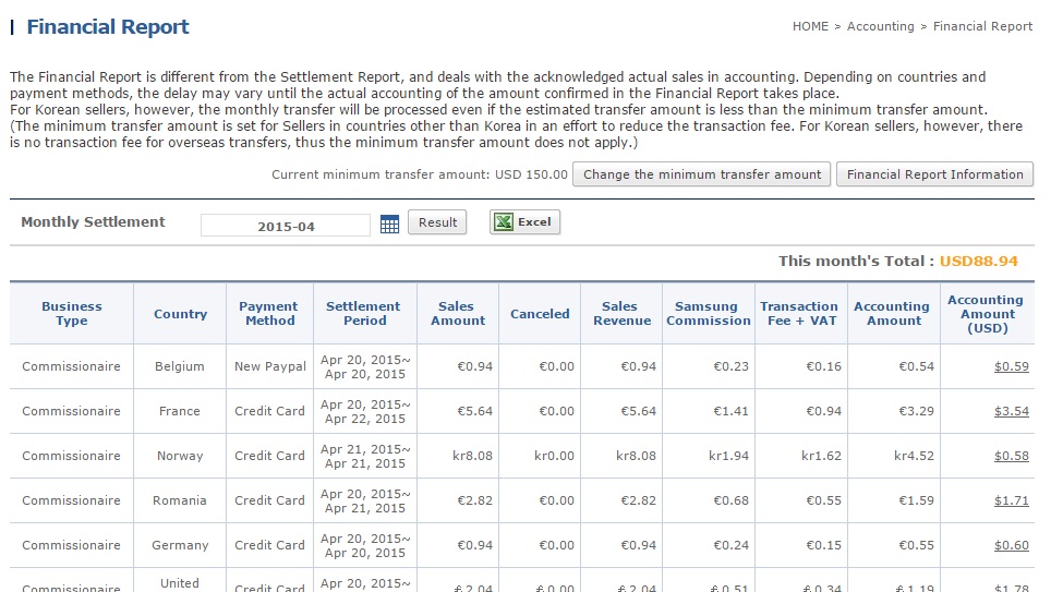
- "Accounting": this is the serious shit where they talk about money. There are 3 subpages - "Sales Summary", "Financial report", and "Settlement Report":
        - "Sales Summary" is more or less detailed information about all your apps' sales.It is detailed, by country and payment type (PayPal, Credit Card, mobile operator, etc,). It does not include any totals though, so it is only useful if you want to thoroughly analyze your sales data, but its totally useless as an overview;
        - "Financial report" is where they "tell" you how much money you earned in the last "period". I am quoting "period", because it is generally monthly, but they don't include the last week or so from the month when they do their calculations. The results are funny - according to these reports, I have $88.94 for April 2015 and $400.81 for May 2015. But in the details, the report for May 2015 contains dates of sales from April. On the other hand, according to their statistics (which are very unreliable), I have $282.45 for April and $628.65 for May in net sales (this is before Samsung's 30% commission and per-country local taxes). Because they don't count the last week or so in the financial report for the month, and I released my app on April 19th, the ~$282 from April only resulted in ~$88 financial report for Aptil. But whether the May's financial report with a total of ~$400 means they own me $400 for May AND $88 for April, or it is $400 for both - I don't know. Are you confused already? I surely am.
        - "Settlement report": Well, I have yet to see this one showing any data. I am assuming this is the report about "how much money we sent you this month". They haven't sent me any money yet. And they haven't issued any "settlement reports" for me either. From what I understand, the deal is that they wait until you make a certain amount of money ($150 by default, which I haven't changed) before they send you anything. And since the "financial report" for April totaled at $88, they must have waited another month (May). But now is June 13th, I have more than 900 sales ($1 each before Samsung's 30% commission and other taxes) until the end of May, And I have yet to see any money from Samsung.

- "Statistics": This is where you can do all kinds of queries about your apps' sales and or downloads. On theory, You can check monthly/weekly/daily app sales/downloads, per app or per country.
Sounds good, doesn't it?
Except it doesn't work.
I mean, it does show some numbers, which probably are very close to the reality, but they definitely are not the real numbers. For example, I know for sure at least one person bought my app from Bulgaria in April (a friend of a friend). Still, today, June 13th, there is no Bulgaria listed in per-country downloads / sales statistics. Which means - they are at least not complete.
Also, for the last 3 months the Statistics broke 3 times. By "broke" I mean "they show 0 downloads/sales from some date on" until I contact their support. Even today, I have no idea how many copies I have sold for the last 3 days.
When they "work", the Statistics show you the number of downloads and the equivalent amount of money your apps have made (before Samsung's 30% commission and local taxes).

So ultimately, for the question "How much money did your app make?" - I have no definitive answer. Neither does Samsung.
The correct answer for the moment is 0, because I haven't received a dime yet. This is for an app, which (according to their statistics, which are proven to not include all the data) has at least 1079 downloads since April 19th.

In short, the whole thing is a big fucking mess. And we're talking about real money here!
In my case it is just a hobby project in my spare time, so I don't really care much - the money are just a nice bonus for the time spent. After all, some money will eventually come some day - I don't know  how much and when. But I can imagine some poor soul (like Belvek EOOD, may he burn in hell) trying to make a living out of this,

So, to stick to the Q&A tradition I somehow established for the "rant" posts, here is an imaginary dialogue between me and a Samsung representative, but this time I ask the questions:

Q: Can I see exactly how much money my app has made?
A: It is complicated. ... OK, you can't.

Q: Can I see my app's ratings in different countries?
A: You can see the ratings for customers who left a comment. But you can't see the ratings given by customers who just rated the app, without leaving a comment. Except for your own country.

Q: Can I get notified via e-mail when a comment from a customer arrives, instead of having to check the site on a regular basis?
A:
We would like to inform you that your inquiry has been registered successfully and sent to the Customer Support team.
We would like to ask you for patience and can assure you that you will get notified about the outcome as soon as possible.
While you are waiting for an answer if you have any further questions, please do not hesitate to contact us again.
A:
First of all, we are sorry for any inconvenience.

We are very grateful for your suggestions regarding our services.

We would like to assure you that our team is doing their best to improve it in order to satisfy the needs of the market, both buyers as well as sellers.

Moreover, your suggestions were forwarded to the Headquarters of Samsung and will be reviewed properly so that the mistakes and misunderstandings are eliminated to the minimum.

We sincerely apologize for the inconvenience occurred.

We believe that all the discrepancies will be corrected in the near future.

If you have any further questions, please do not hesitate to contact us.

Q: I'm gonna strangle you with my bare hands!
A: Nnnn....ggggkh....khhhhh...rrrrrr....

Friday, June 12, 2015

DIY Breakout for ESP8266

This is going to be another one of these geeky posts, which you would prefer to skip, unless you're interested in electronics.
If that is the case - here is the summary: I did this geeky looking thing in the pictures bellow, which makes it easier for me to use another geeky thing to do geeky stuff. It is quite small, it was pretty hard for me to make it (the most difficult soldering I have done so far). It works and I am proud of myself! Bye :)

(top)
(bottom)

If you're still here - this is a tiny breakout board for ESP8266-1.
If you don't know what that is - it is a small and cheap WiFi module, which is becoming the underground hit in the IoT community (and for a good reason). Here is how it looks:

Originally it was marketed as a WiFi module you command from the arduino over serial communication. But people soon found out it is much more than that - it actually is a SoC (system on a chip) with a microcontroller more powerful than the arduino, and with more memory. The problem was that it was pretty hard and inconvenient to program these things, but not anymore - now it is almost as simple as programming the arduino (even from the same IDE). And, these things have GPIO pins, which makes them completely suitable for standalone operation. In short, they are like a more powerful arduino, with built-in WiFi and you can buy 5 for less than $15!
Well, this is for the model  ESP8266-1 with only 2 GPIO pin. But there are many other models, with more GPIO pins. For example: ESP8266-201 for $4.45 (I have one of these ordered, hopefully it arrives today).
To program these things you need an USB to TTL converter and a setup like this:
You must pull some pins high permanently, some pins need to be pulled low temporarily to make it boot into programming mode.
Since I plan to be messing with these a lot, I decided I would replace the breadboard circuitry with something more permanent.
So now it looks like this:
 
I have female headers for the ESP8266, the USB2TTL and handy headers for 2 GPIO pins, ground and VCC (so you can plug stuff there without the need of a breadboard). There are also 2 buttons, to reset it and put it into programming mode. I also have male headers on the bottom, so you can slap it on a breadboard, like this:
 
Running it on battery is possible thanks to this little guy:

It is a 3.3V linear voltage regulator with soldered capacitors on it. And it looks like a small robot with a jetpack and an erection :)
Bending its legs properly allowed me to just put it on the place of the USB2TTL, like in the picture above.
And, you can just run it off the batteries without a breadboard by connecting the battery to the pins at the bottom:


I went through 1000s of problems, soldering it was extremely difficult (for me), but I am too lazy to describe them here (and actually - who cares).
It ended up very well, works fine, and it is quite convenient.

Now it is time to do something with it :)

Tuesday, June 9, 2015

Never dink and DIY!

I am writing this post with somehow mixed feelings.

Today I received 2x transparent breadboards from gearbest,com.

I've decided I must posses one of these the moment I saw them. They were listed in several online stores in my country, but in all of them they were out of stock. My usual site for Chinese parts, www.banggood.com, did not offer them at all. But another Chinese site, www.gearbest.com, where I bought my favorite quadcopter from, just happened to have them in stock. Jackpot!

So, today I received 2 of them, and after some tinkering, my "blank" breadboard now looks like this:


Now, if you don't think this looks super mega cool, please unsubscribe from my blog and never ever come back. You're simply not my target audience.

If you're still here and wondering what the hell is that, I'm not going to explain what a breadboard is. Look it up if you really want to know.
Just for comparison, here is what the actual breadboard looks like:


And here it is compared to a standard breadboard:


This is after I put 2 blue LEDs in the new transparent breadboard. So it is a bit unfair - like comparing a picture of Jessica Alba with perfectly made stage makeup against a picture of Britney Spears with no make up just after she gave birth (or just before that).
But, life is not fair, and us men tend to favor the good looking newcomers, especially if they wear something semitransparent.

So, why the "mixed feelings"?

Everything would be perfect, if I did not suffer casualties during the process of setting up the new breadboard.
I received the new breadboards today at noon. But the weather today was really nice and I went to a really nice restaurant with some very close friends of mine after work. One thing lead to another and I came home decently drunk.
But I still wanted to play with my new toy, so I gave it a go. I moved one of my Arduino Nano's to the new breadboard and connected ground and 5V to the power lines on the top. Then I added the blue LED on the left and I was amazed how awesome it looks (remember I was a bit drunk, so I was easily amazed). Then I decided to add another blue LED underneath the Arduino, on the right,

I don't know what went wrong here. Really. I blame the alcohol. But the result was that I somehow managed to kill the Arduino! It is dead now, and I am pretty sure it is my fault! Here is a picture of the poor chip, lying there lifeless even though it is connected to USB:
No lights are shining, no "tada" sound when I connect it to the USB. It is dead. I killed it. And I don't even have a clue how. It just happened somehow. I am so sorry. I felt terrible.
I am sure if I haven't been drinking it would still live.

Anyway, I was still drunk and still too excited about my new transparent breadboards, so I just took the next spare Arduino, soldered its headers (that was a risky move in my condition), placed it on my new shiny breadboard, connected the 2nd LED and took the 1st picture you saw on this post;

But I have this bitter taste in my mouth. It might be the beers, but it might be the guilt from killing the innocent Arduino.Yes, I replaced it with a new one, but this is like shouting: "The Arduino is dead! Long live the next Arduino!". I am sure I am quoting that wrong :)

This is the first time I ruin something "complicated". Until now, I have only blown  2 infrared LEDs, The first time it was because banggood.com meseed up their pinout. The second time was more like an execution - I was frustrated about how bad the same IR LEDs were, so I demonstrated my son how they burn by deliberately wiring them wrong (actually it was the same wrong wiring banggood.com had shown in their pictures). There was a bit of fire and a cracking sound. It was awesome.
It is like stepping on an innocent animal (e.g. an ant) after you have stepped on a strawberry twice.
It feels bad.

But hey, I got these new transparent breadoards, and they look super mega cool. And I still have enough spare Arduinos to keep me going.

Yet I have learned another lesson - when you've been drinking, it is not only not ok to drive, it's not ok to mess with electronics either!

Good night.

UPDATE: It is not completely dead! When I power it from an external battery it works, even communicates with the PC over USB. So it looks like I have shortened something and killed its USB power lines. But it is not totally unusable.
So, I didn't kill it, I just crippled it - I'm not sure which is worse.
Anyway, even the simplest thing like connecting an LED can go wrong and cause damage. So, just don't touch electronics when you have been drinking!

P.S. Ouch, my head :)

Sunday, June 7, 2015

DIY Custom breakout board

WARNING: This post is going to be too nerdy. If you're not interested in electronics in details, just skip it. So far I have tried not to go into too much technical details, but this post is all about them.
You have been warned.

Now, as I mentioned in my previous post, I am in the process of adding a small LCD screen to the existing arduino circuit for my smart home project. And I ran into some problems. Solving them taught me something I want to share.

But first, let me illustrate the problem. The LCD I am using is a Nokia 5110 LCD breakout. Since it operates on 3.3V, wiring it to a 5V arduino is not trivial. You need logic level converters (or plenty of voltage dividers).
Actually, I did connect it directly to 5V the first time, by mistake. It didn't blow up, it worked. But they say it is not recommended to use it that way.
The "prototype" (for testing the LCD) was a fine mess of jumper wires:

It looks too ugly even for me, but the real problem is that I have to fit it in here:

So I came up with this:
(back side)
(front side)

Which connects the LCD to an arduino like this:


Now you just slap it on the breadboard and all you need is 2 jumper wires to connect it. I counted 24 in the first picture.
Basically, it is a "breakout for the breakout". The LCD came with a breakout board when I bought it (the red PCB). But it still worked at 3.3V. So I made a breakout which wires the LCD breakout through the logic level converter to the "interface" pins.
I cheated a bit, because in the original schematic I used two logic level converters and in my breakout board I use only one. This is because there are 5 signals to convert from 5V to 3.3V and the level converters have 4 IOs. So, out of pure laziness, I wired the reset pin with an inline 10K resistor instead through a level converter like the other 4 data pins. It is OK in this particular case. If it wasn't, I'd simply add another converter like on the first breadboard (and use only one of its 4 IOs).
So far nothing special, it was just what I planned to do.

Except that this time I used a classic proto-board like this:

Until now, I've always used strip-board like protoboards like this:

The classic ones are much more tedious to work with, because you don't have pre-made connections.
You have to make them yourself, usually by bending component leads and sometimes using 3-way or even 4-way solder joints. It is much slower and requires a lot of patience. I had to take a break twice, to cool down my nerves :)
But these boards allow for much more flexibility, and ultimately space savings, which I needed in this case.
Of course, real men don't use protoboards - they etch their own PCBs. And they use SMD components. Some day, when I grow up, I might learn how to do that too :)
Anyway, that was the minor lesson learned - how to solder on a classic protoboard. I really don't want to do it again.

The real "invention" (and the reason I dedicate a separate post to this) came later. Well, I am pretty sure it has been "invented" many years ago, but being the noob I am in electronics, I had to invent it for myself. What am I talking about? Look at this picture again:

Pay attention to the pins at the bottom. Did you get it already? :)

For those of you who didn't here it is:

Normally, breakout boards have their pins next to each other, in one or more rows. And that is exactly what I would do, if I had enough space on the breadboard where I need to put the component, without even thinking. Then I would use jumper wires (9 in this case) to connect the pins on the arduino to the corresponding pins on the breakout, That's what we all have done so many times with manufactured components, that we don't even think about it.
But, by spacing the "interface" pins properly, I can now just put the component on the breadboard directly under the arduino, so the corresponding pins get connected by the breadbord's premade connections. I only need 2 jumper wires to connect the orange and red wire (3.3V and 5V) to the other side of the arduino. The same would apply if I decide to solder this into a stripboard some day.
I guess this "technique" has something in common with what arduino shields do.
It is a very simple idea, but I haven't thought about it before. And it looks so obvious now :)
And I can think of so many cases where using this technique will come in handy.

This is probably just a basic and well known knowledge for people with good experience in electronics.
But reinventing the wheel, as pointless as it is, feels so damn good and rewarding!

Cheers!

DIY "Smart Home"

It is time to brag again. :)

This time it is with my attempt at "Smart Home", which turned out pretty nice.

Here is how the "front end" looks currently:


When you move the mouse to the bottom, the bottom row changes like this:


It shows:
- Date and time (pretty obvious)
- Today's weather forecast (overall for the day in top middle and hourly on the bottom)
- Room temperatures (in the living room and in the terrace)
- The first 2 buttons on the bottom row turn the living room air conditioner on/off, the second 2 are for the AC in the terrace and the other 3 control the vacuum cleaner robot (made by Samsung, ironically).
You can also see one of my two cats in the reflection :)

Room temperature data and IR control are possible thanks to this:


And it is currently located here:


There is also a web page I can access from anywhere, which looks like this:


Not pretty at all, but fully functional and loads fast.
"Billy" is the name I gave to the vacuum cleaner robot, it is short from "Debil" :)

If you're wondering what's the deal with terrace's room temperature and air conditioning - my terrace is closed, so it is like a small room. And I use it as a smoking room, cabinet and lab at the same time. In other words, a "man cave" (as a friend of mine calls it).


Anyway, now I can check the temperature in my home any time from anywhere, and if I wish I can turn the air conditioners on/off. This is quite handy, because my windows look to the west and during the summer it gets quite hot in the afternoons. Instead of turning the ACs on when I get home and sweat until they do their job, I now turn them on shortly before I go home and when I get there, the air is already nice and cool.

I also have live video from my home (so I can watch my cats) and sometimes I see that Billy (the vacuum cleaner) is stuck. It does that sometimes (its Samsung after all). When that happens, it stops and starts beeping annoyingly until you tell it to shut the fuck up. When I am not home and it is stuck (it is programmed to start cleaning at 16:30 every day), it annoys the cats constantly until I get home and turn it off. And I can see that on the video feed - the cats would not sleep (as they usually do most of the time when I am not home). But not anymore! Now I just use the web access to put Billy out of his misery and restore the peace and quiet for the ladies :)

It would be nice to find a way to hide that USB cable better or at least paint it with the same color as the wall. I might do that some day :)
Putting the arduino part in a box would be also cool, but it would have to be a very special box, which lets infrared light through and blocks visible light, to hide the electronics inside. I have no idea what material would that be, where to get it and how to build the box.
Oh, and I need to burn the red LEDs on the arduino or at least stick some black tape on top of them :)

If you're not interested in how it is done, you should just stop reading now :)

Technically, the whole system is a mess of C# (the program that acts as a web server and shows the UI), C++ (the arduino code), some JavaScript and HTML (on the web page).
The arduino part has a temperature sensor, infrared receiver (so it can learn new IR codes and eventually be controlled with whatever remote I have closest to me) and 8 infrared LEDs (to transmit IR signals). I used 8, because I need to cover the entire room (you never know where Billy will get stuck) and I couldn't find LEDs which are wide angle and powerful enough. So I just put 8 in parallel and spread them to point in different directions. Because you can't power 8 LEDs from a single data pin of the arduino, I used an NPN transistor, so they get power from the aruino's 5V pin.
The arduino talks to the C# program over USB. I even made the effort to make the C# part scan through the COM ports and find the arduino.
There are 2 instances of the C# program - one running on the old Asus Eee PC you see in the pictures, and one running on the laptop in the terrace (which is connected to another arduino running the same code, but with only one temperature sensor and one IR LED connected).
The 2 C# programs talk to each other via HTTP requests, because they are web servers anyway, so it was the easiest way.
For the weather forecast I just do an HTTP get request to accuweather.com (just like browsers do) and then get the information I need from the resulting HTML (typical web scraping).
On the laptop in the terrace, the same C# apps runs in "minimized" mode, where it only shows a small (150x150 pixels) black box with two temperatures in it. Double click toggles full screen / minimized mode. Right click when minimized toggles the AC on/off (so I don't have to reach for the remote).

Now I am in the process of adding a small LCD screen to the arduino part on the terrace to show me the time and temperature, so I can still see them when I have something full screen (e.g. when watching a video, playing a game, etc.). Besides, I already have the LCD, so why not :)
I had to solve some unexpected problems to do that, and I feel very proud with the solution! I did learn something, which I believe deserves a separate post (coming very soon).
Update: I did it, here it is:


The whole project was relatively easy, because I happen to have enough PCs at home to do the actual job and use the arduino only to handle sensors and LEDs. But it is not that difficult to do it without PCs involved at all (except the UI part obviously) and use only arduino and ESP8266 (these are very cool WiFi modules, cheap and powerful, look them up if you're interested in electronics). I just don't need to.

The live video stream is not part of this project. I had it set up long ago. It is pretty simple - another old and unused netbook is placed in a kitchen drawer and runs Skype. When I call it, it automatically accepts and turns video on. So when I am at work I just call it via Skype and it picks up. Or I could call it from my phone from anywhere. Simple and effective. At least it was before Microsoft bought Skype and turned it into the piece of garbage it is now. But that is a subject for a separate post (in the rant series).
When someone is home (me or my son) - we just close the kitchen drawer's door to hide the netbook and not feel uncomfortable that someone might be watching. The mic on the netbook doesn't work so no one can listen either.
The only problems (besides Skype crashing on a daily basis) are that I must open the drawer's door and leave the lights on when I leave home. The lights are LED, so they don't consume too much electricity (so bills are not too high and I am not polluting the planet too much). It would be nice if I could turn the lights on/off and open/close the kitchen drawer's door remotely. Some day I'll make it possible :)
Or ... I might just buy a real IP camera with pan/tilt/zoom and night vision and use it instead :)